Hello friends, on to another repair log.
Here we have a Suzuka 8 Hours 2 board, which is a classic motorcycle game from 1993.

Suzuki 8 Hours 2 PCB (Namco System 2)
Check out some gameplay here (well, of Suzuka 8 Hours 1, which is the same with fewer tracks apparently), courtesy The Adequate Gamer on Youtube:
This board came with a partner - we'll do that one another time. Likely a linked pair had been decommissioned together. This one has graphics issues, namely that the red colour was completely missing.

Maybe just a night ride?
Operators will often just let games keep running when something like this happens, it's usually not enough of a reason to pull the game from rotation, especially if it's an older title. First off, I put the board into test mode and pressed the TEST button a few times to get to the screen test. It looked like this:

Black where red should be.
Arcade games typically produce their video signal digitally, then convert to analog RGB. My first step was to check all three colours with an oscilloscope.

Here I am checking the blue line, which produces this waveform on the 'scope:

Blue and green waveforms show a staircase pattern.
Notice how there are 16 steps in this little staircase? Now check back up two pictures and notice how there are 16 shades of blue. Now I'll check the red line.

Looks pretty dead to me!
So we can see here that the red line is doing a whole lotta nothing. So our goal is going to be to trace back from the output line and see what's failing to relay the image. Here's a simple diagram of how the image data gets to the output on a Namco System 2 board. Many other architectures use similar methods.

The Video RAM (VRAM) stores the video data, then sends it to the C116 which generates the proper timing for analog RGBS. The sync signal is also generated here, I didn't show it though. The digital signal conversion is done with some form of a digital-analog-converter, aka a DAC. On older boards, the DAC is accomplished using a R/2R resistor ladder. This is a very simple and reliable setup. It looks like this:
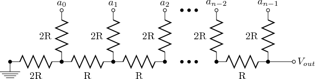
R/2R Ladder (https://en.wikipedia.org/wiki/Resistor_ladder)
On the board you'll see a single-in-line (SIP) resistor pack for each colour (red green blue). You'll often find these broken on boards so keep an eye out for that. Next is the PNP/NPN amp. Again, I've seen these broken, blown up or otherwise.

Here the red VRAM is on the left, then the C116, then the red resistor pack. You can start to see the NPN and PNP transistors at the bottom of the image. Red's transistors are TR11 and TR14.
Back to the repair. The signal was still absent coming from the transistor so I knew it was likely the C116 or VRAM. Checking for signals on the resistor pack (from the C116) I could see that only two signal lines were firing. VRAM is known to fail after a certain amount of time so I decided to poke around there next, hoping that the VRAM was at fault instead of the C116, which would be very hard to find a replacement for.
There's a neat trick you can do with VRAM, which is to simply piggy back another, known working VRAM chip of the same type:

When I piggy backed VRAM onto the blue and green VRAM chips, there was no change on the screen. However, when I piggy backed the working VRAM onto the red VRAM, strange things started to happen:

Signs of life! We see some red on top and some white instead of cyan on the bottom. Not perfect but neither is the connection when you piggy back on to a bad chip. Next step was to desolder the old VRAM and solder in the replacement.


Success! And thus we close another chapter. Oh, wait. Where's the track? Turns out there are also two banks of dip switches on the lower board that configure the ROMs in some way. Here's how they should look:

SW1: 2 and 4 on, others off.

SW2: All on.
Once you've got all that, the track returns, in and finally we see the game in full colour with all the elements.


And thus we close another chapter, for real this time.