
Hello! After a surprisingly long hiatus, I have finally had some time to work on a few more little things which will be posted in the coming weeks. First up I present:
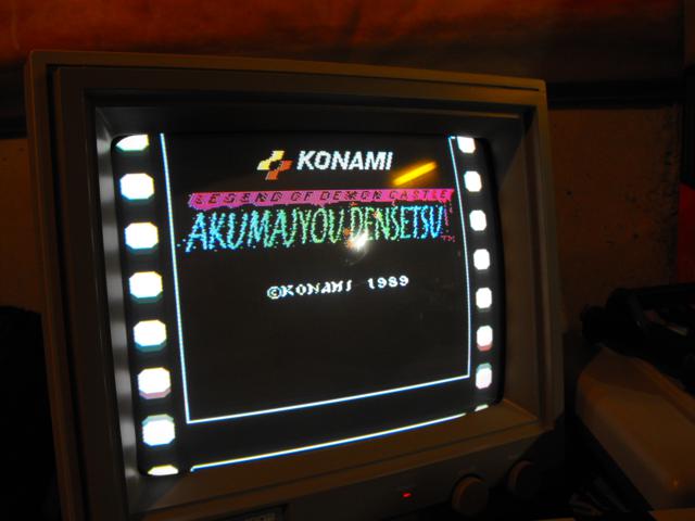
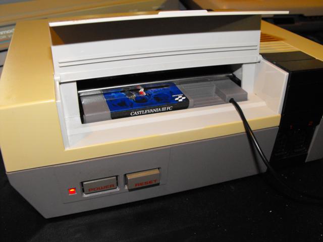
Castlevania III FC: Dracula's Curse with Full Famicom Sound!
The Castlevania series by Konami, which I would argue is one of the most successful series currently in production, holds a special place in the hearts of many retro gamers. Castlevania and Castlevania III: Dracula's Curse regularly show up on top games lists for the NES, with Castlevania at #19 and Dracula's Curse at #5 on IGN's Top 100 NES Games list, for example. Apparently there was a Castlevania II as well.

Dracula's Curse is already known for its kick-ass soundtrack, but what NES players didn't know was that the Famicom's version (Akumajou Densetsu) had a much better sound experience thanks to an on-board audio synthesizer.
So why was the game modified for the NES, which uses a regular old MMC5 chip for memory management? The Famicom pipes the audio signal through the cartridge, giving it a chance to get mixed with another source. When Nintendo redesigned the Famicom as the NES, the opted to relocate the audio path through the expansion connector on the bottom of the system. Basically, there is no way to get an audio signal from the cartridge to the NES without some serious surgery, or a little bit of thinking outside the box (literally).
My goal is to create a Castlevania III game in NES form with this extra audio stream intact.
There are actually three options to accomplish this goal (or get close):
- Buy a genuine Akumajou Densetsu on Famicom, along with a Famicom->NES converter, and modify your NES to act the way the Famicom does. This involves making use of the unused pins on the cartridge connector. You would also have to modify the Famicom->NES converter. This results in the cleanest mod, but my intention here is to eliminate the need for modifying the console. Game will be in Japanese unless you change the ROM.
- Buy a genuine Akumajo Densetsu on Famicom, along with a Famicom->NES converter, and follow this guide to create a mixing cable for the extra audio. This is a good option because it involves no tampering of the (not inexpensive) Akumajo Densetsu cartridge. Placement of the cable might be troublesome though, and the game will remain in Japanese unless you change the ROM.
- Follow my guide to end up with an English language version of Akumajo Densetsu in an NES cart!

- Akumajou Densetsu Famicom cartridge. Not necessarily cheap. Other VRC6 cartridges like Madara will work, but they have bigger PCBs and I'm not sure they'd fit into an NES cartridge along with the converter.
- A PCB-only Famicom->NES adapter. Easiest solution for this is a Gyromite cartridge or other early NES game. I'll cover that below
- A length of audio wire.
- 2 470-ohm resistors.
- A solder-type male phono plug, and a solder-type female phono jack.
- A 27C010 EPROM and a 27C020 EPROM if you want to replace the chips with the English translations.
- A cartridge label if you want it.
- The cartridge is held together with 5 flathead screws. From the end label, the parts to the left and right of the label will be flat. The more common cartridges have 3 security screws and clips that are visible from looking at the end label. None of these 3-screw cartridges will have a converter.
- When looking at the individual pins, a cartridge containing a converter will have an offset nib. If the nibs on the pins in your cartridge are in the center of the pin, it will not contain a converter.

- Remove the original ROMs. The bigger, 32-pin ROM is the PRG ROM (2Mb, or 256KB) and the smaller 28-pin ROM is the CHR ROM (1Mb, or 128KB). You can do this by cutting off the ROMs with a Dremel or you can desolder them if you have a lot of patience. Refer to my other tutorials for more info on this step.
- Patch the Japanese Akumajou Densetsu ROM with the translation from the link above. Use Lunar IPS to apply the test and retest with an emulator to make sure it worked. Don't use a Castlevania III ROM, it won't work.
- Split the ROM using a NES ROM utility like tnines with the command (assuming your rom was called akumajo.nes) "tnines -s akumajo.nes" to get the "akumajo.prg" and "akumajo.chr" files. Discard the "akumajo.hdr" file.
- Burn the smaller CHR ROM onto the 27C010 EPROM, and burn the bigger PRG ROM onto the 27C020 EPROM.
- The PRG ROM is a drop-in replacement. Just pop it in and resolder, no rewiring necessary.
- The CHR ROM is a little more complicated. Here's what you have to do:
- Bend up pins 1, 2, 24, 31 and 32 and clip them a little bit (but not too short, you still need to solder to some of them)
- Solder a wire into hold on the board where the EPROM's pin 24 will go
- Now insert the EPROM and solder down all the pins that you didn't bend up
- Solder your wire from hole 24 to pin 2 of the EPROM
- Now solder a wire from the bent-up pin 24 to a ground. The spot I normally use is pin 16 of the EPROM which would be the last pin on the left side of the chip.
- Finally, strip a length of wire about 1cm long and solder a wire that bridges the between pins 30, 31 and 32. This basically gets power to pin 32. Pin 31 is not connected to anything so you can solder across it just fine.
- Test and make sure it works!


- Start by taking the jackets off both the male and female connectors.
- Usually you'll see that the ground connectors are quite long. Here you want to trim them such that the size of the adapter will be reasonable, but also such that you can solder together the grounds to create a structural bond.
- Solder together the grounds, trying to make some sort of structural strength so the adapter won't just snap apart.
- Take one of the 470-ohm resistors and solder it in between the two signal pins on the plugs.
- Now take about a foot of audio cable (which has one insulated wire and one bare wire for ground). Solder the ground to your ground lug on the adapter, and solder the insulated wire to the side of the resistor connected to the female RCA plug. It would certainly help to create some sort of strain relief inside but it's a tight fit already.
- Take the heatshrink and cut it to the length of the adapter. Look at some commercial plugs to see how much room you need to leave on each side to ensure a connection. Cut a small hole in the heat shrink and fish the other end of your audio wire through it. Don't actually put the heatshrink over the adapter yet.


- Drill a hole in the top right corner of the NES cartridge you intend to use. Make sure you do it towards the top, because the mechanics of the NES might prevent you from clicking the cartridge into place if you put the hole too low.
- Fish your wire through the hole you drilled on the NES cartridge and route it down to the Famicom->NES adapter area.
- Locate pin 45 on the parts side of the Famicom->NES adapter. Use some sandpaper to remove the green masking on this pin below where the black adapter extends to.
- Shorten up your remaining 470 ohm resistor and solder one side to pin 45.
- Solder your signal wire to the other side of the resistor at pin 45, and solder your ground wire to any ground on the board. Check my picture below for the location I used.
- Gently test your interconnect to see if you have full sound. If you do, good job! If not:
- If you have no sound at all, the problem must be with your adapter. Make sure you soldered to the right side of the resistor. Try plugging your TV/stereo/whatever back into the NES alone and make sure the NES is working properly.
- If you only get partial sound, try to identify whether it is from the NES or the cartridge. If it's from the NES, your connections to the Famicom->NES adapter or wire is faulty. If it's from the cartridge, your adapter is faulty.
- Using a hot glue gun, fill up the adapter gap so it's nice and sturdy. Be sure everything is the way you like it before you do this obviously.
- Slide (or pull, more likely) the heatshrink into place and shrink it with a hair dryer (on a high setting) or heat gun. Careful not to melt the glue again.
- Trim your heatshrink if you can't insert the plugs all the way. Do this using a box cutter (ie X-Acto Knife).


Finish up the project
Now all that's left to do is reassemble your cartridge and attach a label. Refer to my other tutorials on how I do my labels. Here's what I used for artwork:
That's it! Hope you had fun!
