
Black Tiger is a platformer from Capcom in 1987, and also goes by the name of Black Dragon in Japan. We'll be working on a pair of bootlegs.

The game has some interesting adventure features like buying weapons and collecting keys to open doors. Personally, I think the graphics are iconic of late 80s games with some big sprites and fluid little animations. The control is nice and responsive, allowing you to navigate the levels nimbly. I think the music is fun too, but I don't think everyone would agree.
Apparently Black Tiger was slated for a Nintendo NES home release, but no prototype has ever been found. A few screenshots do exist here at Unseen64. Several home computer releases did get made. Surprisingly, the lo-fi looking Commodore 64 version looks like it would be the most fun. Here's a comparison of arcade and home computer versions:
I only have a paltry few upright arcade games in my collection, but one of them is an old Stern cabinet that came with a Black Tiger marquee. After playing the game for a bit I decided I wanted to finish the conversion. The cabinet was in bad enough shape that I didn't feel bad for removing the last remnants of the "Berzerk" stenciled artwork on the sides. So the hunt was on for some Black Tiger boards!

New CPO ready to go!
So, I ended up with two boards because I jumped on a good deal for an untested bootleg, and nearly simultaneously I found I already had a Black Tiger in a box of untested boards. As you can see, they're very similar, but not identical.
Brothers? Board 1 on the left, board 2 on the right.
Board 1
Symptoms: Sometimes has major video problems, sometimes works for a while but glitches and freezes, has sprite issues.
Got this from a fellow collector/fixer as untested. Sort of played but mostly garbage on screen. I poked around a bit and for some reason everything just worked itself out. I chalked it up to a loose ribbon connector. I tossed it on in my Black Tiger machine, in anticipation of my nieces and nephews coming over for Easter dinner. They're young enough that they only know about arcades from "Wreck It Ralph". After an hour or so in attract mode, the sound quit. I restarted the game, and it acted normal for a while, but then the floor fell out from beneath the hero. He languished in the unknown for a few moments then the game froze. When I reset it again, we were back to how the board initially came - if you were to cut the screen into 4 equal columns, numbers 2 and 4 were straight garbage, and 1 and 3 were showing some semblance of gameplay. This generally indicates that the CPU board is happily trudging along but video board is bad. Check out these graphics below that (roughly) parcel out the character (text), object (sprite), background, sound, and CPU sections of the boards. Colour is also taken care of in the CPU section near the edge connector.


These are common for a lot of Capcom boards, like 1942, Ghosts N Goblins, etc.
By shorting data pins, I found there was some vertical mixing going on near the text section. For example, shorting a pair of data pins on a latch might cause the background layer to tile itself in columns. This was a good spot to start checking more carefully, using the brute force method (the alternative method being to start with schematics and trying to figure out the problem from there).
PROTIP: Let's talk a little bit about the brute force method. I call it brute force because it involves simply checking all pins on all chips and can be very time consuming, but often leads you to the right (bad) chip. My preference for a tool is an oscilloscope, but in most cases a logic probe will do just fine. The basic philosophy is "all connected inputs should show activity". An extension of this is "all outputs where the inputs are connected should show activity". For example, let's take a common chip, the 74xx86, which is a "Quadruple 2-Input Exclusive-OR Gate". Meaning there are 4 elements, where each has two inputs and one output that follows the XOR function table. Like an OR, but if both inputs are high, the output is low. So we come across an '86, and check all the pins for activity. First, we notice that pins 1, 2 and 3, which are Input 1, Input 2 and Output (for the element 1 of 4) are floating. Must be a bad chip right? Well, we have to check the board to see if those pins are connected anywhere. In many cases, all four elements may not be used. So let's say we look and indeed, they are disconnected lonely pins. So no problem there, we skip it. Next, we check pins 4, 5 and 6 (element 2 of 4) and notice that the output, has activity. Ok cool, that element must be fine, right? Maybe not. Check both inputs to see what they're doing. If either are floating (anything that's not 0V or 5V, often seen to be around 1.5V or so in my case), something is wrong. Follow floating inputs back to whatever chip is outputting it. But let's say one is pulsing and one is low. Reasonable inputs, but think to yourself.. why would they have used XOR gates with a constantly low input? Try a few things with the game itself, like resetting it, actually coin up and get into the game, make sure there isn't just some condition where the suspiciously low input comes alive. For example, joystick inputs are often not taken when in attract mode. Once you're convinced the low (or high!) input is suspicious, follow it back to the last chip and perform the same procedure. OK back to Black Tiger #1.
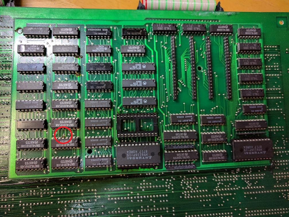
I found a seemingly missing input on a whole bunch of 74LS86 (Quad XOR gates). Like in my above hypothetical, it was low, not floating. Traced back to a 74LS08 (quad positive AND gates) where one of the two inputs WAS floating. I had a hard time finding the source of this, eventually traced back through the ribbon connector to the CPU board to a 74LS14, practically in the opposite corner of the CPU board. This is a hex inverter chip. I nudged the related input pin and hallelujah! everything popped back into place. This must have been what I poked the first time that got the video sorted out. Bad solder joint? Maybe, but I replaced the '14 anyway.
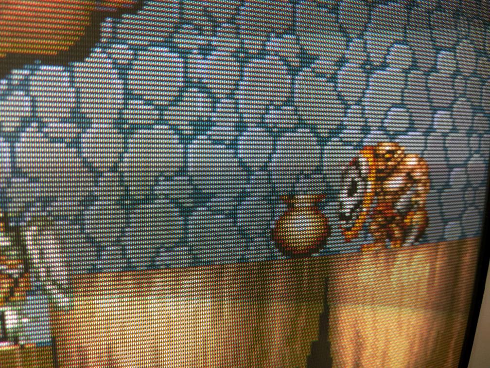
Next, one quarter of some sprites, like the dragon and the first enemy were showing glitches.

"Blargggarble"
I focused on the sub-board that does the sprites. The glitches seemed to be correctable by adjusting the 5V line lower. However, going too low started bringing up glitches on the background layer. Observing that this bootleg PCB was practically devoid of bypass capacitors, checking the 5V line on the sub-board showed a lot of noise, maybe popping some element of logic over a threshold that doesn't get reached when I crank the power down below 5V. Adding some of the 220uF caps gave me a bigger window of voltage level to get both the sprites and backgrounds working. OR SO I THOUGHT. I realized while setting the voltage to adjust out the glitch I had settled on something at about 4.9V, which isn't normal, and would result in crashes. I started touching chips with my hands and when I gripped this one '157, the error disappeared. Tried resoldering the chip to no avail, so I replaced it with another. The removed '157 tested good in the IC tester, so I put it back. I followed the inputs of the '157 back to a '161 which weirdly had a leg that had been bent out, but not connected anywhere in particular.
Bent leg
Since it was a counter preset input I figured it would be grounded. My guess was that the machine that placed the chips kinked it out, and it was repaired by hand by bending the leg to a 90 and soldering through the hole on the bottom of the board. This connection was faulty and jumping it to then next pin (also grounded) finally fixed the issue.
"I said, do you like my old-world urn"
Board 2
Symptoms: Very dark video, showed random text on screen often.
Found this one in a box with other boards, nicely wrapped in antistatic foam. Video amp issue on the CPU board for sure, everything was very dim. This board is missing a trace that board 1 has. Weird!

Top: Board #2, older, missing a trace. Bottom: Board #1, with said trace.
Started with the video problem. The video is generated from some RAM on top of the board, then output to some '367 latches and a resistor ladder. Some of the resistor ladder nodes were dead. Found the '367 corresponding to green was completely dead (and confirmed bad). Replacing that brought back the green, but blue and red were still mostly dead.

What is this, the Amstrad CPC version?
This one puzzled me a bit. I found one of the bits of the SRAM was stuck low, but it looked like the chip providing the data was working fine. I poked around eventually found another '367 (the one driving the red signals) was bad, and it was pulling the node low all the time, whether or not the chip was enabled. This time it was a single element, not all of them. OK now we have that nice big "B" of the title blue again.

OK now we're up to the Commodore 64 version.
Still no red, but at this point I could take a wild guess and assume the red's '367 was probably bad. Pulled it and yes, it was bad, but didn't fix the problem. Ok, home stretch. I decided to measure between the resistor networks that make up the DAC. Board #1 had resistors just bussed together. This board had some sort of a SIP resistor array marked "1030". These three networks all read differently so I pulled them all.

Burned out SIP resistor array
Of the three, only the green (which had been the strongest colour) measured anything reasonable, and even then seemed iffy. I grabbed the Ghost N Goblins schematics (which... may be basically identical to Black Tiger... wish I had noticed that earlier), and the network was spelled out as 100, 220, 470, 1k and 2.2k ohm, all bussed to the output R, G or B pin on the edge connector.

Old school DAC
Actually, board #1 has one extra resistor at 4.7k, but it goes nowhere so it's not necessary to hook up. I built the networks from their component resistors, like so:

Resistor Centipede
And finally, we have full video again.

OK lastly, some inputs were stuck. In test mode, it's obvious to see which ones:

If it's not obvious, it's 1P Shoot 2, 2P Right and 2P Shoot 2
The way inputs are handled on Black Tiger are different from Ghost n Goblins so that was no help here. However, it was easy to deduce that each input was sent to a '245 transceiver, and also tied to 5V through a resistor (this is known as a pull-up resistor - intended to make sure the logic sees only solid high and low logic values). The resistors looked good so I checked the '245s. Two of them were bad, in different ways. One was easy to figure out (which fixed 2P Right), because the input was stuck low, regardless of whether the button was being pressed. The other could have been difficult since it was the output side that was broken. The chip was still behaving, so it showed activity on the output pins, but this was simply activity appearing on the same bus from other chips. Whenever dealing with transceivers ('244, '245, etc) be wary of this possibility. You'd need to use a logic analyzer to positively identify this problem. Anyway testing both of these '245s showed several of the eight elements were broken. Replaced the '245s and MAYBE IT'S FINALLY OVER.
Welcome back, Black Tiger Twins!
BONUS ROUND:
I thought it would be funny to change the warning text that appears when you first turn on the game. I accomplished this simply by reading the first EPROM, looking for text using my favourite hex editor HxD, and changing it, being very careful not to change anything else. Black Tiger contains no ROM checksum tests so I didn't bother trying to fix that.

Oooh politics