This board comes from a fellow enthusiast who had taken a crack at it with no success. Luckily he installed sockets in a lot of places which should make some things much easier to diagnose!
The schematics are available (although a little fuzzy) in the manual. Missile Command runs on a 6502A CPU, like several other Atari boards. So the first thing we want to do is check all the bare minimums on the CPU. Turning on the board showed a solid blue screen and no activity on any pins on the CPU, besides the watchdog circuit resetting the CPU on its own about twice a second.

Why did I bother to post this picture
You can see this on pin 40 of the CPU which is the reset signal. If it's not watchdogging, this should stay high. The nice solid blue screen indicates the video generator (well, at least the sync) is working as intended, but on the CPU you would at least expect to see a clock signal on pin 37, which was missing.
Turning to the schematics, we see that the clock signal comes from an OR gate (74LS32 at C4). On the input side, I could see a good clock signal and what looked like a poor low input, maybe around 1.5V, but the output was stuck high. At first I suspected the OR gate was bad, so I replaced it to no effect. The output of the OR was not stuck high, rather it was seeing the second input (1.5V) as high, so the output was high all the time. Thus no clock was getting through.

You're naughty!
This naughty signal was called ∅EXTEND and has something to do with pausing the CPU for a time at the end of each frame. It comes from a flip flop (74LS74 at H6), and I could see that both the normal and inverted outputs were weak, as in not particularly close to 5V or GND, so I switched it out for a good one. The one I took out tested bad with my tester.

Bad stuff
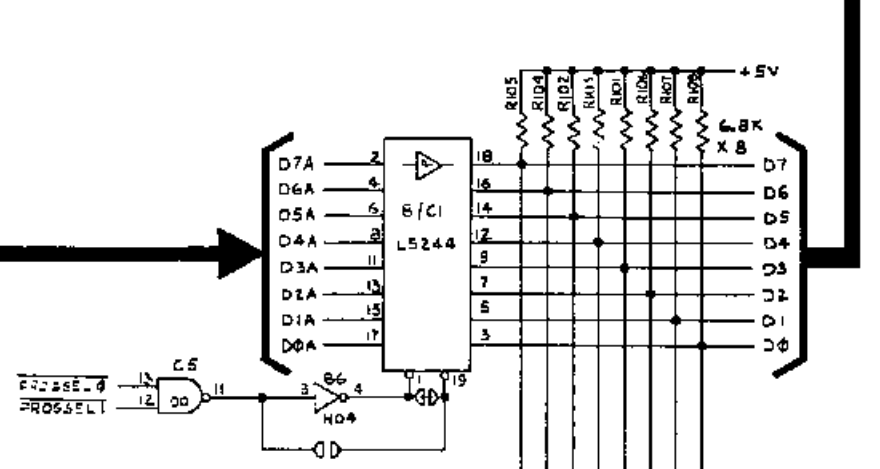
OK now we were at least getting a clock signal to the CPU, but no apparent change otherwise, even the watchdog was still going. I tried the test mode (activated by shorting the TEST terminal to ground) but no luck. Probing around the CPU, everything was pretty much dead so I swapped it out for another 6502A that was sitting around. This time, I started to see activity on some of the ports. However, I quickly noticed that some of the address pins were squashed, so I went after the related buffer (74LS244 at F2) and started seeing healthy signals.
However, now I've gone from a solid blue screen to a constantly flashing blue screen. Next, I checked the data lines from the CPU and found that they were also in contention.

Signal line in contention - square waves indicate data, but it's not strong enough to switch the logic.


Examples of healthy signals. Note the weird one on the right. This can be hard to nail down as good or bad if you don't see clear signals. This seems to happen on signals that are at the end of a chain of logic, probably a result of differing voltage output levels on the ICs.
I noticed activity on a ROM line that should have been silent, so I removed all the ROM sockets and found a bridge between the a pin socket and a trace running beside it. This is a big issue on these Atari boards with no solder mask on top.
With the ROM sockets fixed up, I tried the "test mode" again, which I figured wouldn't work with the video still blank. But, it puts out some tones on the speaker to let you know if the DRAM is working. There are 8 DRAM chips, called DRAM 0 to DRAM 7. The tones were indicating that DRAM 0, 2 and 7 were bad. I noticed that a few pins were showing continuity that shouldn't on DRAM 2 so I removed the socket to find another bridge.

Tiny solder bridge
I checked the sockets for 0 and 7 but they were OK, but still sounding as bad by the test mode.
At some point while working on the RAM or ROM I heard a familiar crack that sounded like an IC releasing the magic smoke, and I lost the test mode, back to a solid blue screen. I'm afraid this is going to lead to trouble! Found the '42 at E8 to be causing trouble using the HP comparator.

HP Comparator, useful tool
I didn't know it at the time, but this was a rather important fix, as proper operation of this '42 is necessary to stop the watchdog timer from resetting the board continuously.
Replaced, getting random noises from the POKEY now. Checking the data lines from the 6502 again, D7 was stuck in limbo. This is the main data bus that is connected to a lot of stuff. With the board off, and measuring the resistance of the pin to 5V, the D7 node was about 400 ohms instead of about 6.8k for every other channel.


Indication of a failed IC connected to D7 since the pull-up resistor is measuring 423 ohms in-circuit, but 6.8k out of circuit. Other data line resistors measured 6.8k in-circuit.
Checking the schematics, indeed all data lines should be pulled up to 5V by a 6.8k resistor when not in use. I removed the resistor and checked but it was OK so it seems likely that some connected IC is partially shorted to ground.
All
I replaced the connected components until the bus started looking normal. This ended up being a '244 (P10). I actually replaced all the 244s at this point since they were all the same vintage.
This finally brought me back to the point I was at before - no video but the test mode tones telling me that DRAM 0 and DRAM 7 were still bad but at least now I was pretty confident the CPU was able to reach most parts of the board. I removed the rest of the RAM sockets and finally found another little tiny bridge. Removed this bridge, reinstalled the socket and all the RAM and we're back in business!

Glorious
I returned this to the owner, and it was working for about a week but went dead again. When it worked, it had a weird issue where using the trackball would cause the screen to lose sync. So stay tuned for part 2!
PART 2
Got it back failed again, this time reporting all RAM bad in the test mode and no activity in the normal mode (well, the screen was constantly flashing indicating a continuous watchdog reset).
I was wary about the 74LS42 I had replaced earlier at E8, since I had taken it from another ancient board, and since that '42 was responsible for disabling the watchdog. It tested bad! So I found another, newer '42 and put it in, and it worked again.
I was 90% sure the trackball-causes-sync-loss issue must be something to do with the owner's cabinet wiring. But just to rule it out, I rigged up some rotary encoders to stand in for the trackball since I didn't have one. Lo and behold, when I rotated an encoder, the monitor lost sync!
Using the schematics, I traced it around and found it was only the horizontal sync that was getting confused. The final horizontal sync signal used for CSYNC is called H SYNC * and is from the output of a '74 at A9. I happened to notice that pin 1 which is a signal called P1R25 which is used all over the board and is supposed to be tied high through a resistor, was going low when I rotated the encoder. So I pulled the chip and found another small bridge! I didn't make note of exactly what signals were being bridged but it just so happened to include the controls. Anyway, turns out this was a chip I replaced, so this bridge was my fault!!
With this (hopefully) final fix, the cities of Missile Commandland should now have a chance at surviving.